Zojirushi coffee maker audio mod
Background
I recently received a Zojirushi coffee maker as a gift, after doing pour-overs for years. While I love the ritual of doing a pour over, it can get fairly monotonous after a few years.
The internals of the Zojirushi coffee maker are very simple and I’m sure it’s the same design as most budget-friendly coffee makers. It consists of a single heater element for both the water and the hotplate, controlled by a single normally-on thermostat. During the brew cycle, the water cools the thermostat and boils up, then re-condenses over the coffee grounds. Once the heater runs dry, the specific heat decreases and the thermostat quickly warms up, tripping the thermostat. Once relatively cool, the thermostat trips on and resumes its hot plate heating cycle, indefinitely keeping the coffee warm. It’s a simple system that works great.
I wanted to create an alarm that can let me know if the coffee maker was left on for too long. Also given that this is a Zojirushi product, I wanted it to play a little jingle when turned on and when complete. I decided to modify the coffee maker by including a simple board to:
- play a song during start-up
- detect the current of the heater and detect the heater’s falling edge
- when the water heater is tripped off, it should play a song indicating the coffee’s done
- when left on for too long, I want it to sound an alarm
I also wanted to do this completely non-destructively and keep the coffee maker relatively stock and revertable to its original form.
Prototyping
Since I want this to be revertable, using a non-contact current sense would be the best choice. I have a couple current transformers (CTs) that I’ve salvaged and they will work for measuring whether the thermostat is switched on or off, since it’s non-invasive and relatively safe.
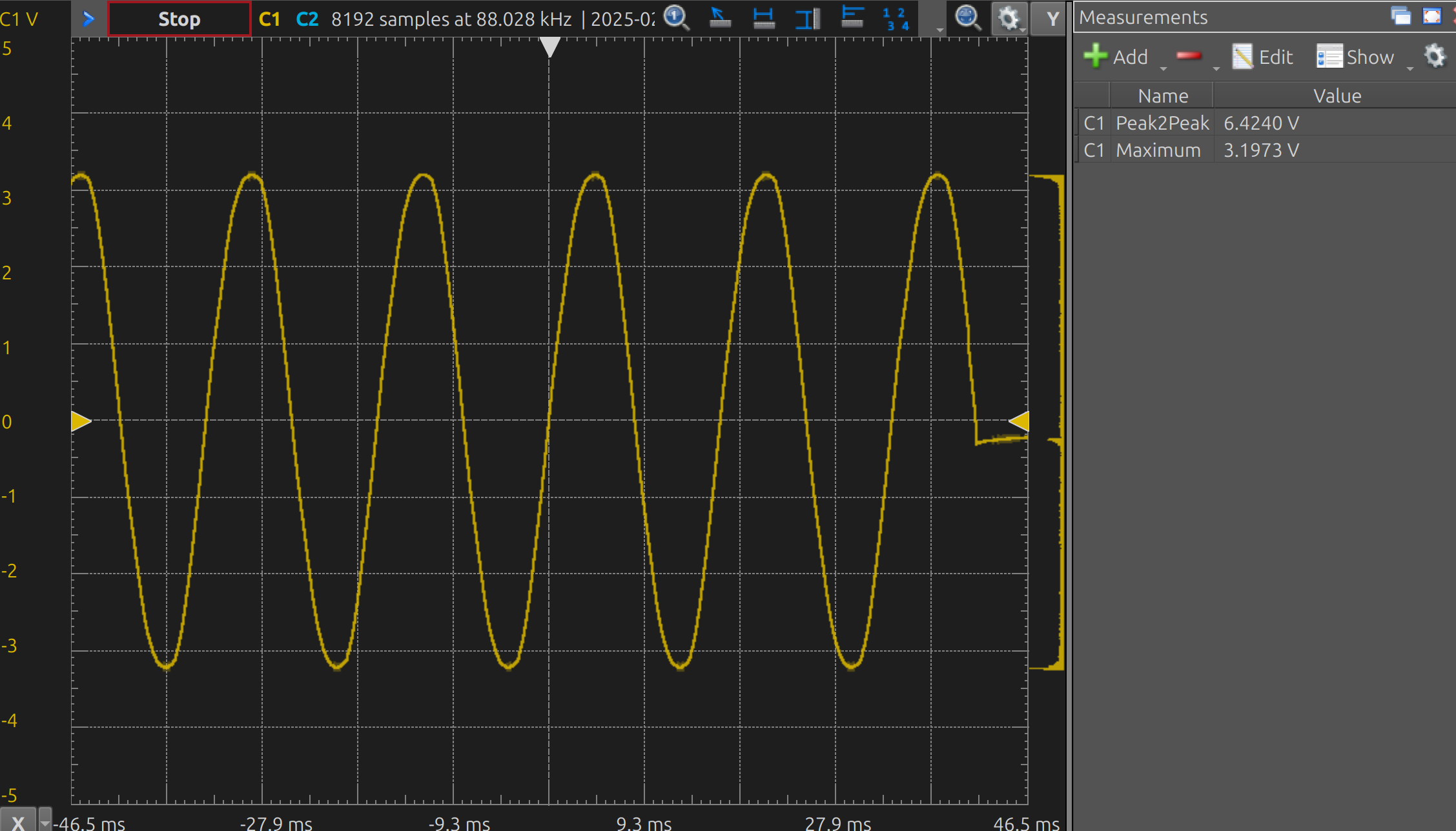
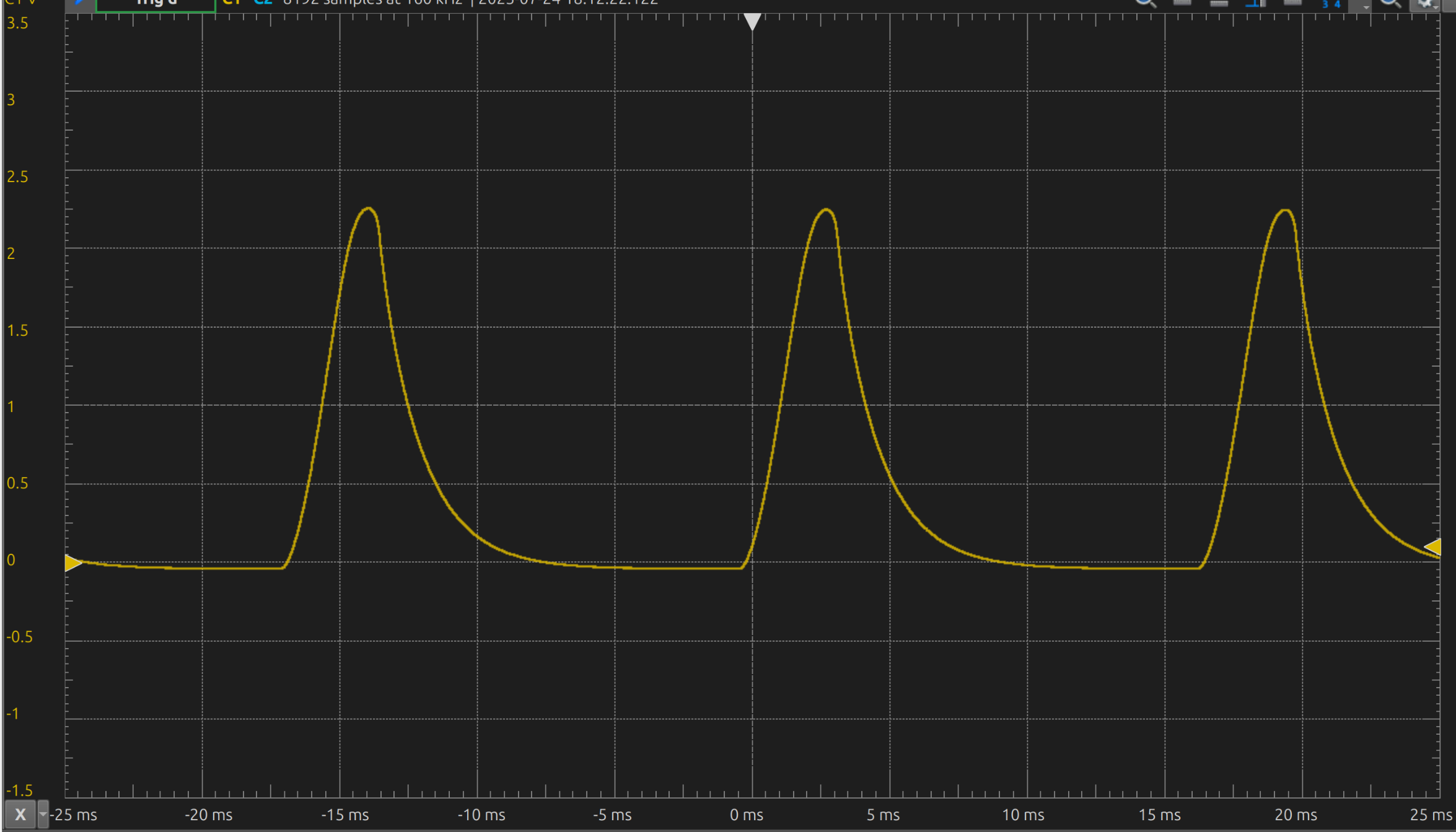
I initially just stuck the CT inline with a 10k resistor and probed it, just to see what the wave looked like (it was as-expected for a resistive heater, but skewed a little from stray effects).
Design
The system can be divided into a few parts:
- power supply (120 VAC to 5VDC and 3V3)
- current sense (the CT) to DC-ish
- microcontroller with piezo buzzer
Board outline
I borrowed a flatbed scanner to get the board outline (surprisingly, it was 1:1), then used a set of dividers and a ruler to get the precise measurements. Then I imported the image into Inkscape and created an SVG of the outline using bezier curves, which I could then bring into KiCAD. Then, I printed out a 1:1 copy, cut it out, and confirmed it fit in there.
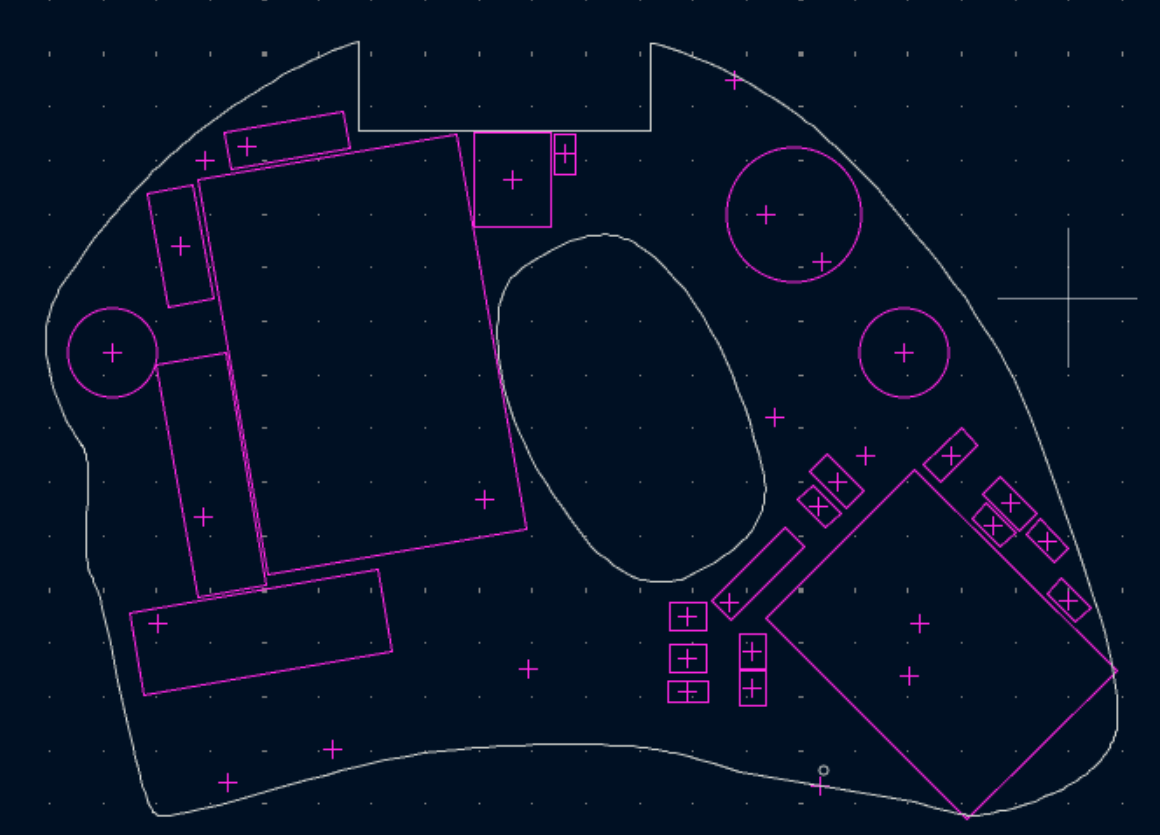
This was by far the easiest solution of getting the outline. I initially tried to sketch it by transferring measurements between the coffee maker into CAD, but that was painstakingly slow and I couldn’t replicate the curves easily enough.
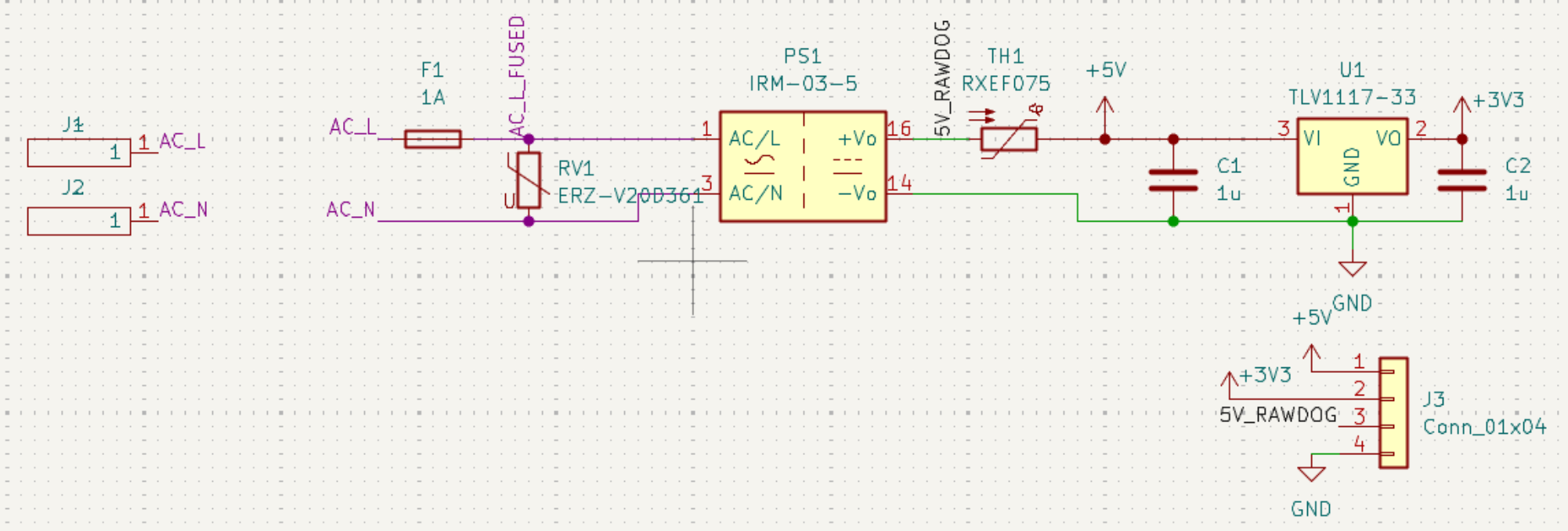
Power supply
I’m just using a 120 VAC to 5VDC module from Meanwell with more than enough current to supply the microcontroller (max of like 100 mA). For protection, I added a fuse and MOV on the 120 VAC side, then added a thermal fuse on the 5V side. Then used a 5V to 3V3 LDO to supply the microcontroller.
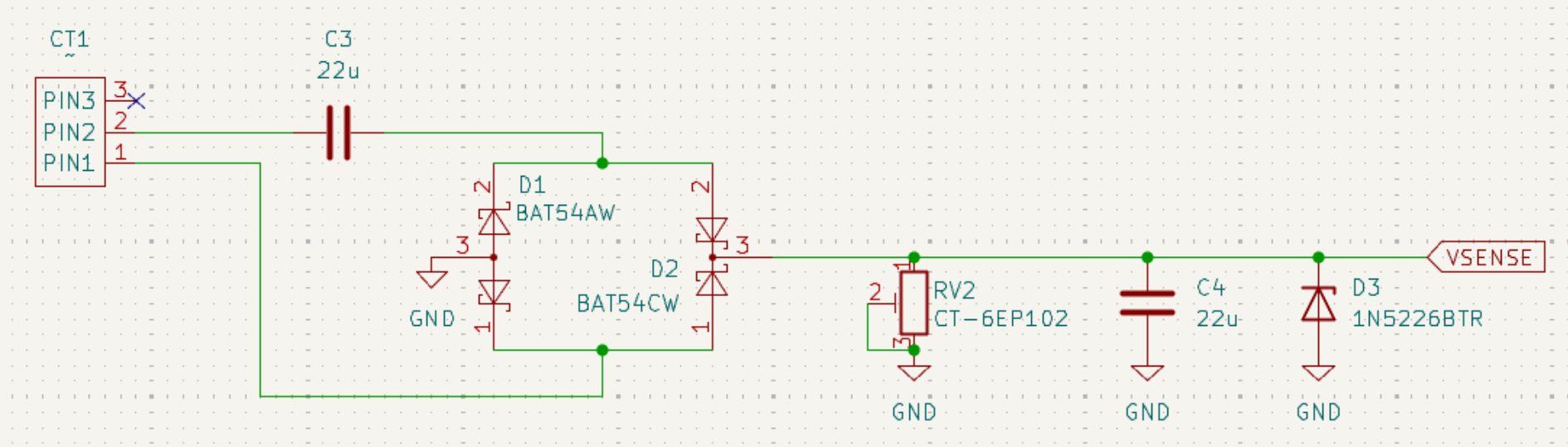
Current sense
The current sense is a current transformer, going across an AC coupling cap. This is fed into a full bridge rectifier, then dropped across a small resistor, then fed into the ADC with a diode in reverse for overvoltage protection. I originally had an RC filter here to read the DC voltage (i.e. rectifying to dc), but the ADC is fast enough to sample at 60/120Hz—so instead, I’m reading the half waves.
I simulated the CT using an AC current source with a series resistor in SPICE, and while this worked, it wasn’t simulated very well. There were several major differences in simulation vs reality, probably attributed to the nonlinearlity of the CT and diodes. Although it wasn’t super accurate, it helped me get ballpark estimates of components without having to do some of the math.
…but wtf?
After rectifying, the frequency should’ve been 120 Hz, since the negative side should’ve been flipped upward. But for whatever reason (bad solder joint? did I solder the wrong component?), it’s still reading 60 Hz.
MCU and buzzer
The MCU is laid out just like the application example from the TRM.
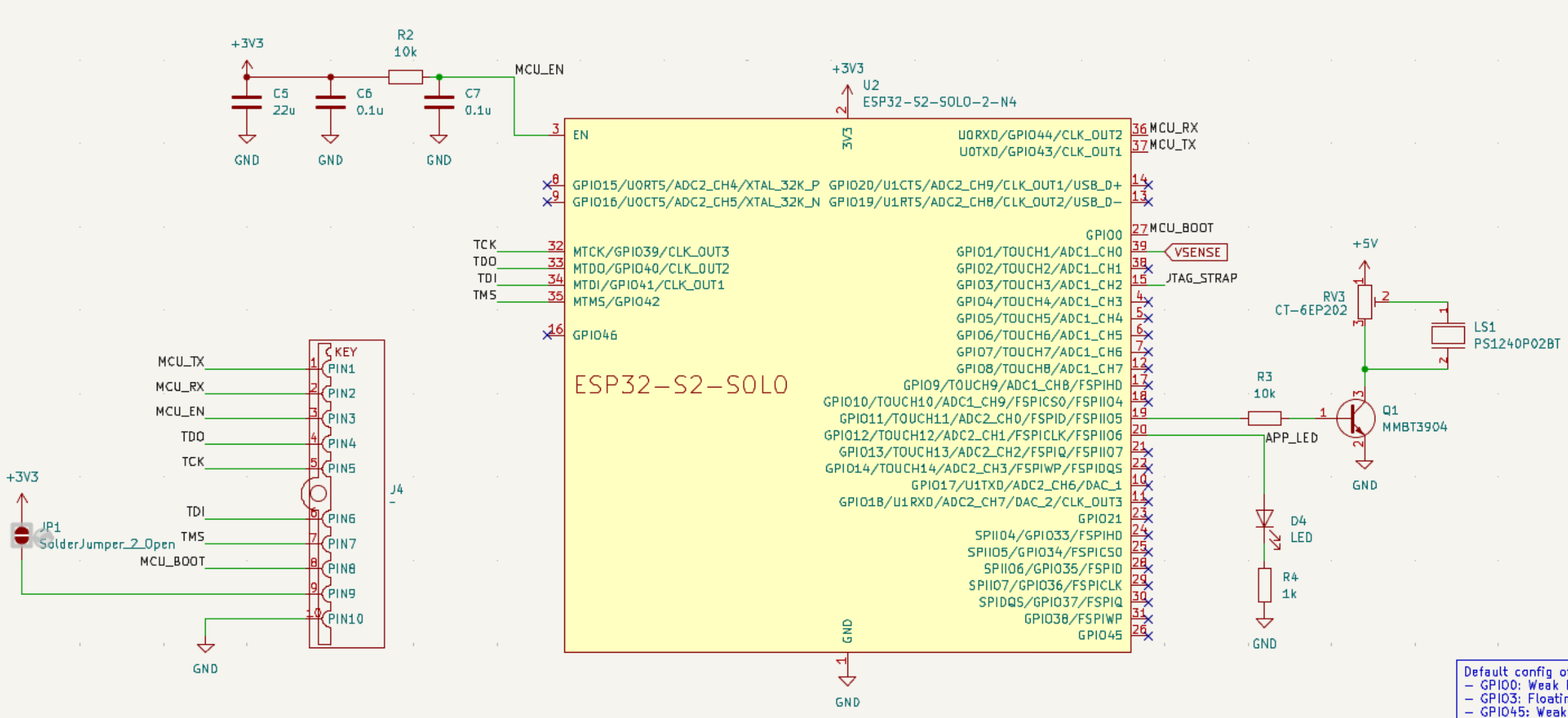
The piezoelectric buzzer is fed by the 5V power divided by a variable resistor, controlled by a BJT on a PWM pin. While this works, I found it still to be too quiet. This was also simulated in SPICE at several audible frequencies.
Software
There are two main components of the software:
- the firmware that runs on the esp32s2
- the user application, a webapp exposed by the esp32’s softAP
Firmware
The firmware is pretty simple and consists of mostly timers:
- on startup, the startup song is enqueued and played
- on the falling edge of the current sense (i.e. when the heater is first turned off), it plays the `done’ song and begins the alarm timer
- there’s some debounce happening w/ timers
- this can only get trig’d after 5 seconds after boot
- the alarm timer plays after 15 minutes of being started
- this timer auto-reloads, so it plays every 15 minutes after the coffee is finished brewing
Protobuffers
I finally had a fun use for protobuffers! I’m using them to hold the track data:
syntax = "proto3";

message AudioEvent {
  // the frequency (Hz) or rest if 0
  int32 frequency = 1;

  // the duration of the note/rest in ms
  int32 duration = 2;
}

message AudioSequence {
  // track name
  string name = 1;

  repeated AudioEvent events = 2;
}
It was honestly easier than expected to use protobuffers. I used protoc to generate both the C and TS code and it worked well for this purpose. It lets me easily transfer the tracks between the frontend and the fw code, as well as giving a convenient format for storing the tracks in NVS.
Misc./ESP-IDF bugs
I noticed there were several bugs in ESP-IDF, although these might just be HW limitations or problems on my part:
- the digi adc calibration is off by a factor of 1/2
- when in continuous mode, it’s using the digi adc (unlike oneshot which uses a different realm)
- the digi adc is limited to 12 bits, but the one shot uses 13 bits - but the calibration routine only seems to use 13?
- bug report
- the adc’s threshold interrupts do not work on the esp32s2
- supposedly, you can set a min/max threshold on the adc to interrupt the cpu
- when doing an ota update where the partitions are not properly defined, calling
esp_ota_writeon a nonnull handle provided byesp_ota_beginwill hard crash and trigger the wdt- I don’t feel like diving into this since I don’t intend to use the ota functionality much
- I think this has to do with aligning the ota0 partition but I don’t feel like diving into this one
- I regret getting the 4MB version, since I like to use 2MB factory/ota sizes. Should’ve gotten the 8MB version
;_;
- not a bug, but there’s no simd instructions on the s2 series, unfortunately. I was hoping to read the continuous adc via dma, then use the vector instructions to find the half-wave rms voltage. But alas, I had to just use
for-loops
Putting it all together
Here’s what the board looks like in the enclosure:
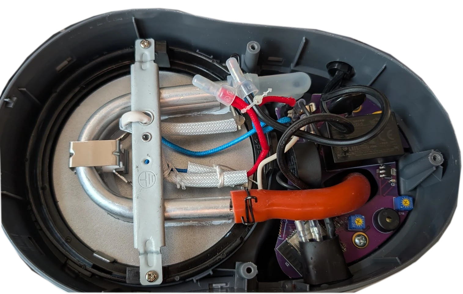
For the power pins, I’m using the same-sized spades as the original. The wire-to-board connectors I’m using have two spades on them, so none of the heater load is going across a trace.
Other modifications
I’m tempted to put in a ground but I don’t want to have to change out the cable or strain relief yet. Both the hotplate and enclosure cover are aluminum, and I can see a potential hazard if the spades disconnect, and either the live/neutral can short to these. I also would like to put a conformal coating on the board, but I might save that for the next revision (if ever).