Dell D6000 dumb dock thing
A few years back, I found a cheap USB-C dock on Craigslist. It had a partly broken USB-C plug but I decided to grab it because it was cheap.
When I got home, I cracked it open and noticed it seems to use a regular USB C-to-C cable to connect the laptop to the dock. When I tried using several cables, I noticed that none of them worked! It seems that the cable did not abide by the USB spec. I used some USB-C breakout boards to trace out the schematic. It seems that Dell (or Bizlink or whatever OE they use) chose to use a non-compliant, custom and propietary USB cable. What kind of monster does that? Is it for greater power delivery? Planned obsolescence? I cannot find a reasonable explanation for this.
Finding the pinout
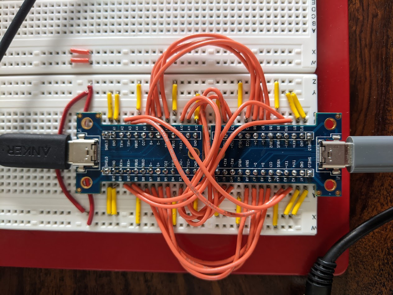
As stated, I just used some breakout boards to find the pinout: literally probing each pin on the breakout board and seeing where it goes. It turns out the entire cable is mangled as fuck and somebody, somewhere, chose to fuck the thing up. The RX pins go to RX again, instead of TX, the CC pins are weird, and the data pins are reversed. I’m assuming the dock’s PCB “corrects” the pinout, so that a proprietary pinout can be used.
Bringing it into KiCAD
I brought the design into KiCAD, for a much cleaner diagram. This schematic is slightly different than what’s above, since a USB cable is meant to be plugged into the receptacle on one side (so the RX/TX pins are somewhat “corrected”).
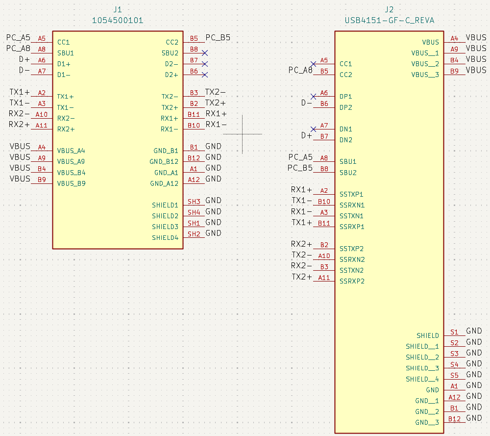
Note that this adapter is unidirectional, at least on the dock side. This is discussed here.
Testing
Initially, I ignored the impedance requirement for the adapter and only matched differential lengths. I think it ended up being around 50 ohms (ish), but when I tested the maximum speed, I couldn’t achieve anywhere near GbE speeds despite a GbE connection. I’m guessing this has to do with the impedance matching.
I created a separate PCB design, hoping to get this printed on a long flex PCB strip. But unfortunately, when I estimated the impedance using openEMS, I was nowhere in the realm of 90 ohms. I might just be doing the simulation wrong, but I’m wondering if this is even remotely possible on a non-impedance controlled (read: cheap) flex PCB. Bleh.
Next steps
I built an adapter that works but it’s pricey af and time-consuming to iterate on the design. I’m hoping that someone with more time and motivation can finish up the project.
The next steps are:
- lay this out on a long flex pcb strip
- create a 3d printed part for the receptacle
- create an assembly containing the part above and the pcb
- get a handful manufactured
- ????